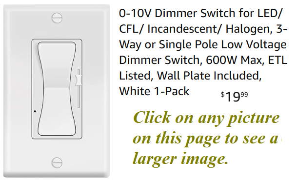
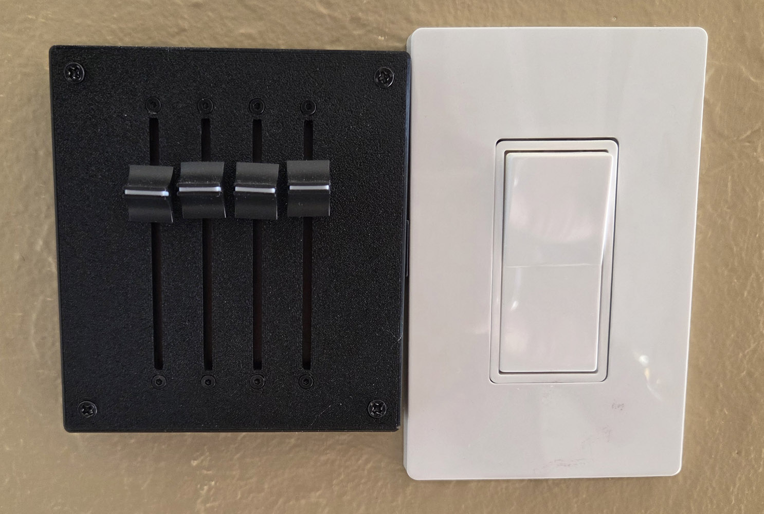
 The dimmer switch I used (at least at first) is shown here and was purchased
here.
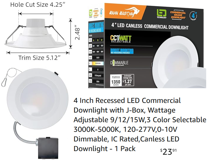
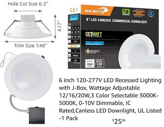
Note that this dimmer can't be used with the traditional 3 wire lights. It can only be used with the lights
shown above or similar ones that advertise "0-10V dimming". I hooked up the dimmer wires from all four
lights in the room to the dimmer switch as per the instructions. The dimmer worked, but I wasn't
happy with the performance. When I moved the dimmer slider from the top to the middle of the range the lights
dimmed by a barely noticeable amount. Even when I moved the slider down more to the 1/4 position the dimming
amount was still quite small. So most of the control, from close to full brightness to
off happened during the bottom 1/4 of the slider travel nearly wasting the top 3/4 of the travel range.
This makes it touchy to adjust the brightness to the desired level. That was the defect that inspired me
to design my own dimmer.
The dimmer switch I used (at least at first) is shown here and was purchased
here.
Note that this dimmer can't be used with the traditional 3 wire lights. It can only be used with the lights
shown above or similar ones that advertise "0-10V dimming". I hooked up the dimmer wires from all four
lights in the room to the dimmer switch as per the instructions. The dimmer worked, but I wasn't
happy with the performance. When I moved the dimmer slider from the top to the middle of the range the lights
dimmed by a barely noticeable amount. Even when I moved the slider down more to the 1/4 position the dimming
amount was still quite small. So most of the control, from close to full brightness to
off happened during the bottom 1/4 of the slider travel nearly wasting the top 3/4 of the travel range.
This makes it touchy to adjust the brightness to the desired level. That was the defect that inspired me
to design my own dimmer.
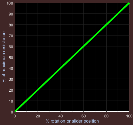
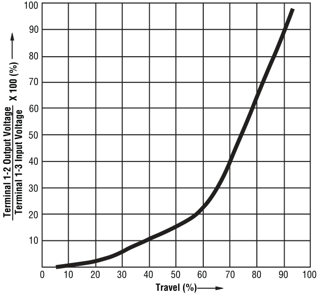 If we plot the resistance of a typical potentiometer as a function of the knob angular position we get a
plot such the one on the left. This is called a linear taper potentiometer.
(It won't be this perfect, but this is the ideal.) It would not be ideal to use such a potentiometer to
control the sound power to a speaker. The first half of the rotation would increase the sound level from zero up to
pretty much the maximum because we don't hear much difference between max power and max/2. This means we are essentially
wasting the 2nd half of the rotation. In most circuits, the potentiometer controls amplitude instead of power.
Since power is proportional to the square of the amplitude, the control is improved somewhat but we can still get
better control of the volume by using a different taper. Instead of a the linear resistance curve the resistance should
increase exponentially.
If we plot the resistance of a typical potentiometer as a function of the knob angular position we get a
plot such the one on the left. This is called a linear taper potentiometer.
(It won't be this perfect, but this is the ideal.) It would not be ideal to use such a potentiometer to
control the sound power to a speaker. The first half of the rotation would increase the sound level from zero up to
pretty much the maximum because we don't hear much difference between max power and max/2. This means we are essentially
wasting the 2nd half of the rotation. In most circuits, the potentiometer controls amplitude instead of power.
Since power is proportional to the square of the amplitude, the control is improved somewhat but we can still get
better control of the volume by using a different taper. Instead of a the linear resistance curve the resistance should
increase exponentially.
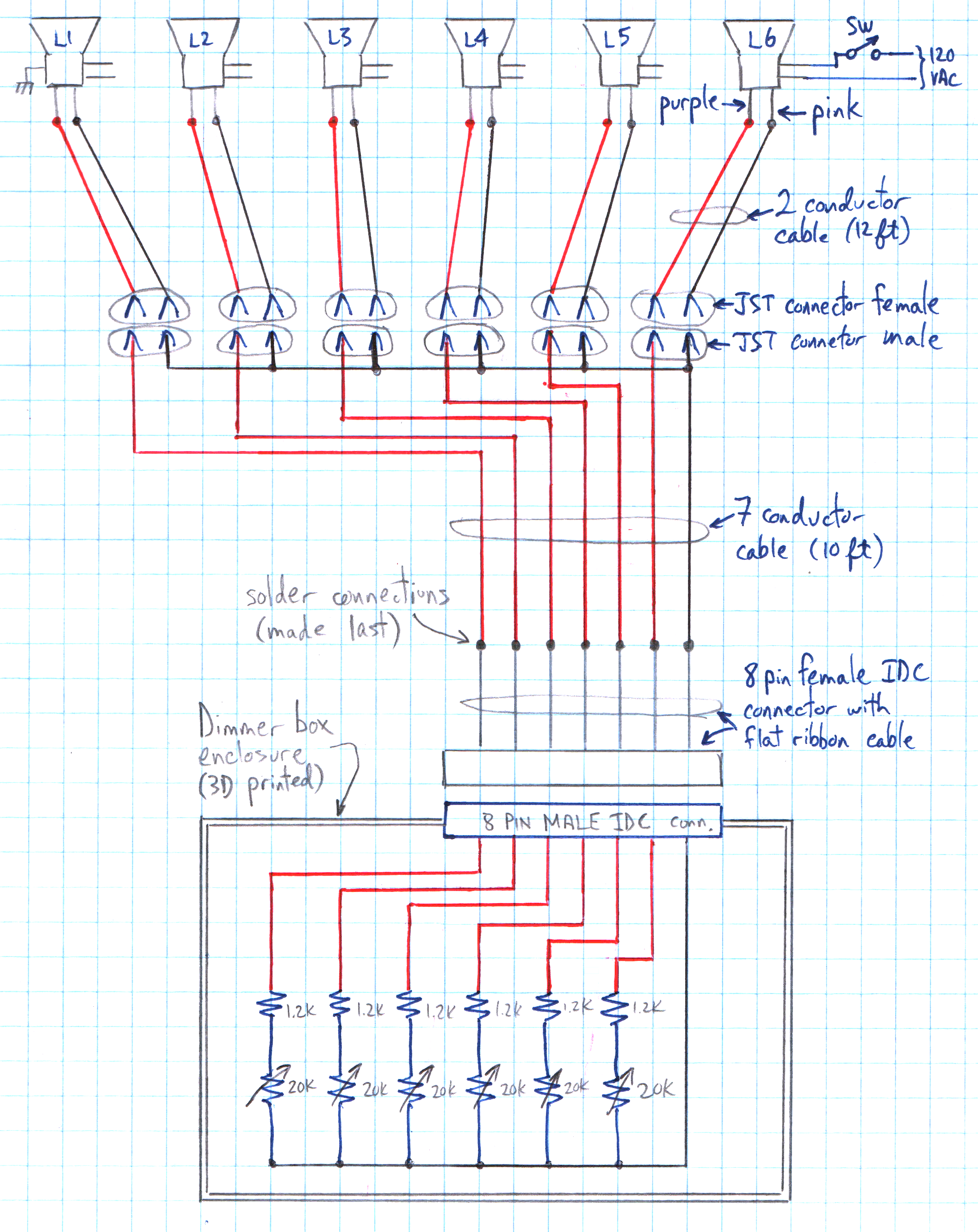 Here is a schematic of my six position dimmer which I installed in my family room and master bedroom.
(The schematic for the four and two position dimmers is the same with some of the lights and sliders removed.)
Here is a schematic of my six position dimmer which I installed in my family room and master bedroom.
(The schematic for the four and two position dimmers is the same with some of the lights and sliders removed.)
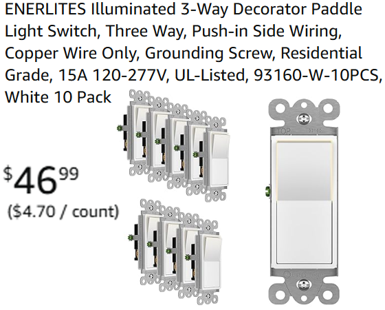
 Since I have already discussed the lights, I'll start with the switch shown at the top right of the schematic.
I bought the switches shown on the left because they were inexpensive and I liked the style and the fact
that they are illuminated when the switch is off. Amazon also sells a single pole version (about 10% cheaper)
as well as a single switch (for $9.69) if you don't need the 10 pack. This inexpensive switches worked well
for the rooms with 4 or 6 lights (a total of 60 to 120 watts). But in the kitchen and hallways, with just
2 of the four inch lights (a total of 30 watts), these switches did not work well. They are still safe and
effective in turning the lights on and off, however the switch illumination flickers. I believe this is because
the switch was designed to be used with higher wattage lights. The flickering is not dangerous, but it is
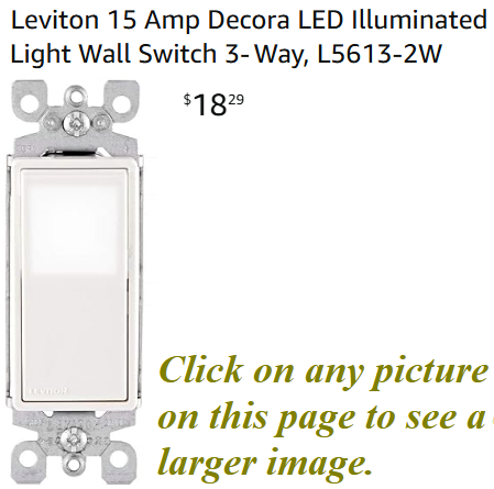
annoying, so in this low wattage situation I used the switch shown on the right. No flickering with those, the
only drawback is that this switch is more expensive. The 120VAC power is connected to the lights and the switch
using standard electrical practice appropriate for the electrical code in your area. (These lights and switches
are also compatible with 240VAC and so no changes to this dimmer circuit are required if you live in a country
that uses 240VAC house wiring.)
Since I have already discussed the lights, I'll start with the switch shown at the top right of the schematic.
I bought the switches shown on the left because they were inexpensive and I liked the style and the fact
that they are illuminated when the switch is off. Amazon also sells a single pole version (about 10% cheaper)
as well as a single switch (for $9.69) if you don't need the 10 pack. This inexpensive switches worked well
for the rooms with 4 or 6 lights (a total of 60 to 120 watts). But in the kitchen and hallways, with just
2 of the four inch lights (a total of 30 watts), these switches did not work well. They are still safe and
effective in turning the lights on and off, however the switch illumination flickers. I believe this is because
the switch was designed to be used with higher wattage lights. The flickering is not dangerous, but it is
annoying, so in this low wattage situation I used the switch shown on the right. No flickering with those, the
only drawback is that this switch is more expensive. The 120VAC power is connected to the lights and the switch
using standard electrical practice appropriate for the electrical code in your area. (These lights and switches
are also compatible with 240VAC and so no changes to this dimmer circuit are required if you live in a country
that uses 240VAC house wiring.)
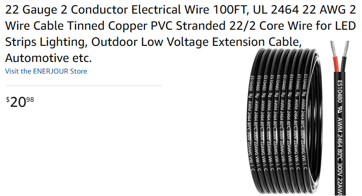
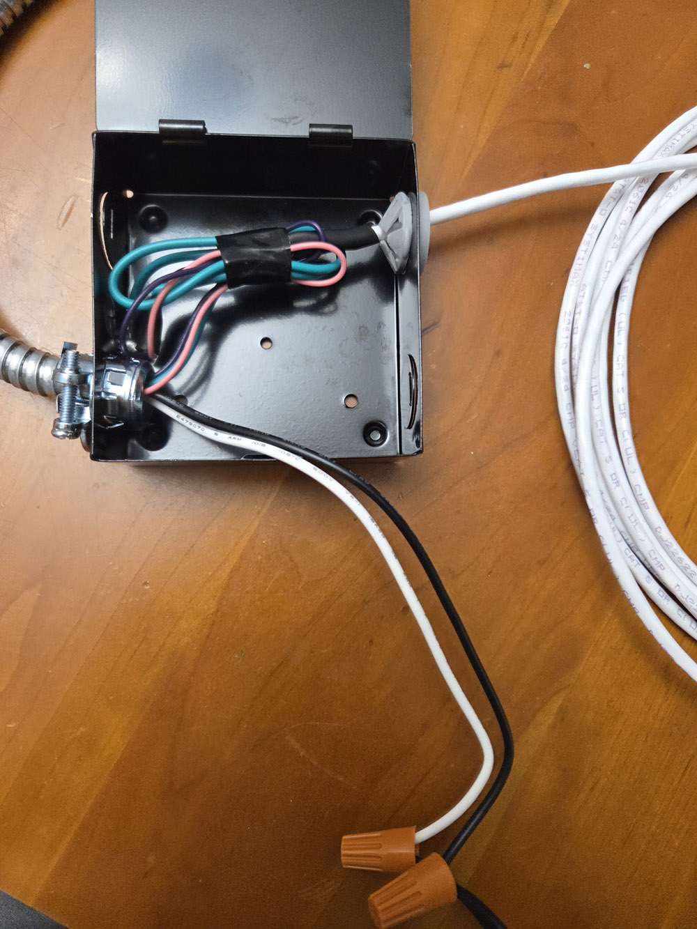 The six 12 foot cables coming from the (pink and purple) light dimming wires use this cable shown
on the left. The picture on the right shows the 10 foot cable attached to one of the junction boxes
that comes with each light. (The aluminum conduit going off the left side of the picture is attached
to the lamp.) The black and white wires are connected to AC power with the two orange lug nuts, but
this was just temporary to test out the lamp and dimmer circuit. Of course when installed the white
and black wires would be feed thru a metal bushing inserted into one of the junction box openings.
Although I used the black cable shown on the right
(purchased here)
for later builds, this was the first one I built
and I used the white wire shown here which I happen to have laying around. The green wire normally
goes to the third wire ground but my home is older and was not built with a third wire ground
(except for a few circuits in the kitchen). So I just bundled up the green wire along with the pink
and purple dimming wires to keep it out of the way.
The six 12 foot cables coming from the (pink and purple) light dimming wires use this cable shown
on the left. The picture on the right shows the 10 foot cable attached to one of the junction boxes
that comes with each light. (The aluminum conduit going off the left side of the picture is attached
to the lamp.) The black and white wires are connected to AC power with the two orange lug nuts, but
this was just temporary to test out the lamp and dimmer circuit. Of course when installed the white
and black wires would be feed thru a metal bushing inserted into one of the junction box openings.
Although I used the black cable shown on the right
(purchased here)
for later builds, this was the first one I built
and I used the white wire shown here which I happen to have laying around. The green wire normally
goes to the third wire ground but my home is older and was not built with a third wire ground
(except for a few circuits in the kitchen). So I just bundled up the green wire along with the pink
and purple dimming wires to keep it out of the way.
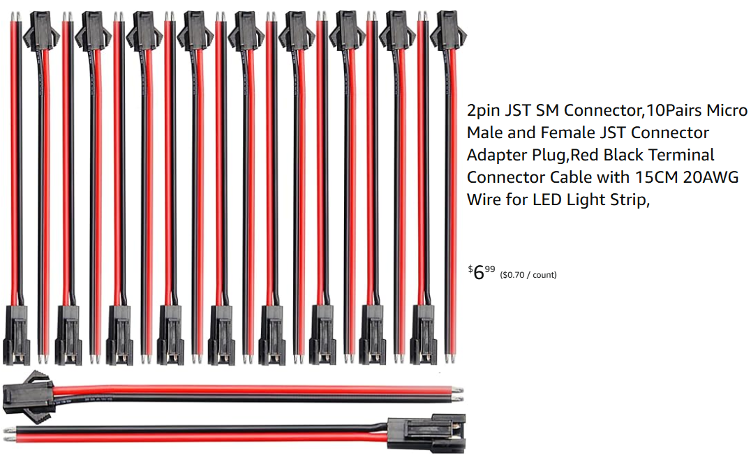
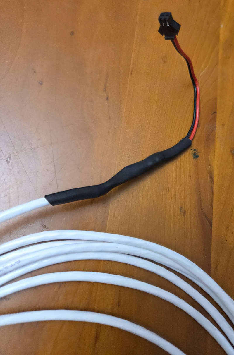 As you can see from the picture on the right, the female JST connector is connected to the other end of
the 12 foot 2 conductor cable coming from the light. During installation, all six of these female JST
connectors will be gathered together near the light closest to the on/off switch where they will be
connected to the male JST connectors attached to the 7 wire cable shown below. Although my diagram calls
for all six of the 2 conductor cables to be 12 feet long I didn't actually build it that way. For a very
large room a few of the cables might need to be even longer. Also the lamp closest to the switch doesn't
really need a cable at all and the female JST connector could be connected directly to the pink and purple lamp
dimming wires.
As you can see from the picture on the right, the female JST connector is connected to the other end of
the 12 foot 2 conductor cable coming from the light. During installation, all six of these female JST
connectors will be gathered together near the light closest to the on/off switch where they will be
connected to the male JST connectors attached to the 7 wire cable shown below. Although my diagram calls
for all six of the 2 conductor cables to be 12 feet long I didn't actually build it that way. For a very
large room a few of the cables might need to be even longer. Also the lamp closest to the switch doesn't
really need a cable at all and the female JST connector could be connected directly to the pink and purple lamp
dimming wires.

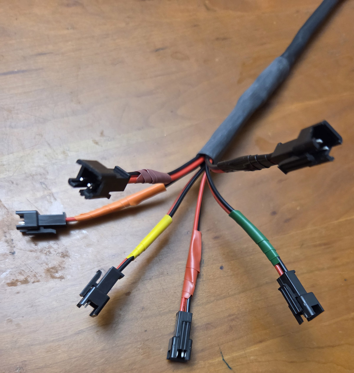 Next it's time to build the ten foot 7 conductor cable.
I used the cable shown to the left and
purchased here.
On one side of the cable I attached 6 male JST connectors.
The colored electrical tape just below each JST connector (on the picture to the right) are not covering up
any electrical connection. The tape is just there to identify the six different lamps. On the other side of the
ten foot cable I attached one of the IDC connectors shown below. I cut one of the cables in this set in half
and used one end or the other, split the 8 wires apart on the ribbon cable, stripped the insulation and soldered
it to the 7 conductors of the 10 foot cable and protected all the connections with shrink tubing. The first time
I built this cable I attached the 8 pin ribbon cable before installation. However it was too difficult to thread
the cable from the attach down to the switch box so I ended up cutting of the ribbon cable part, then twisted the
7 wires together to create the smallest footprint possible to snake the cable from the attic down to the switch box.
Once the cable was sticking thru the switch box, I reattached (soldered) the ribbon cable and again protected
it with shrink tubing.
Next it's time to build the ten foot 7 conductor cable.
I used the cable shown to the left and
purchased here.
On one side of the cable I attached 6 male JST connectors.
The colored electrical tape just below each JST connector (on the picture to the right) are not covering up
any electrical connection. The tape is just there to identify the six different lamps. On the other side of the
ten foot cable I attached one of the IDC connectors shown below. I cut one of the cables in this set in half
and used one end or the other, split the 8 wires apart on the ribbon cable, stripped the insulation and soldered
it to the 7 conductors of the 10 foot cable and protected all the connections with shrink tubing. The first time
I built this cable I attached the 8 pin ribbon cable before installation. However it was too difficult to thread
the cable from the attach down to the switch box so I ended up cutting of the ribbon cable part, then twisted the
7 wires together to create the smallest footprint possible to snake the cable from the attic down to the switch box.
Once the cable was sticking thru the switch box, I reattached (soldered) the ribbon cable and again protected
it with shrink tubing.
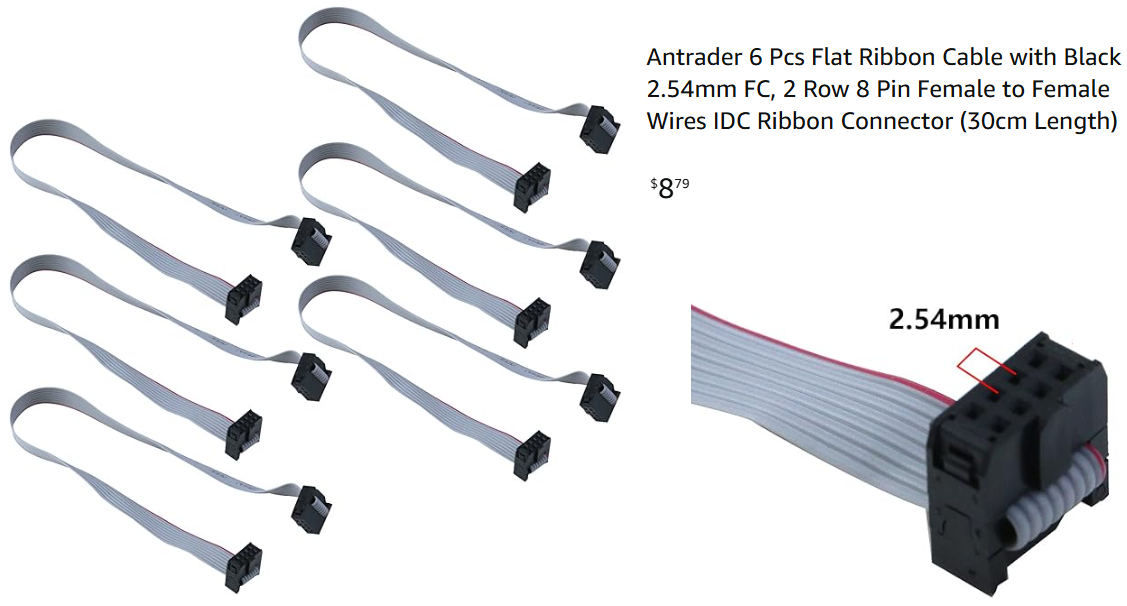
 Since I was planning on building and installing nine of these dimmers in my house I bought the 6 pack of ribbon cables
shown to the left and
purchased here.
I cut each cable in half, so this pack would allow me to build 12 cables since I could use either end. As I mentioned
above, the best construction technique was to thread the 7 conductor cable from the attic to the switch box next to
the dimmer box and then solder the wires of the 7 conductor cable to 7 of the 8 wires on the flat ribbon cable using
heat shrink tubing to insulate and protect each connection. The first time I built one of these dimmers I preplanned
what each terminal of the 8pin IDC connector would be used for (i.e. which light would be controlled and which
slider in the dimmer box would control that light). That was the reason for the colored tape in the figure above.
But after the first time, I realized it was much simpler not to plan any of that ahead of time. This means that
I didn't need the colored tape since any of the 6 JST connectors could be used to control any of the 6 lamps.
This also meant that the six potentiometers (as well as the common ground) could be connected to any pin of the
IDC connector at random. It was fairly easy to identify which connections needed to be made when soldering the
8 pin ribbon cable onto the 7 conductor wire (one wire at a time) to insure that the mapping between potentiometers
and ceiling lights was logical.
Since I was planning on building and installing nine of these dimmers in my house I bought the 6 pack of ribbon cables
shown to the left and
purchased here.
I cut each cable in half, so this pack would allow me to build 12 cables since I could use either end. As I mentioned
above, the best construction technique was to thread the 7 conductor cable from the attic to the switch box next to
the dimmer box and then solder the wires of the 7 conductor cable to 7 of the 8 wires on the flat ribbon cable using
heat shrink tubing to insulate and protect each connection. The first time I built one of these dimmers I preplanned
what each terminal of the 8pin IDC connector would be used for (i.e. which light would be controlled and which
slider in the dimmer box would control that light). That was the reason for the colored tape in the figure above.
But after the first time, I realized it was much simpler not to plan any of that ahead of time. This means that
I didn't need the colored tape since any of the 6 JST connectors could be used to control any of the 6 lamps.
This also meant that the six potentiometers (as well as the common ground) could be connected to any pin of the
IDC connector at random. It was fairly easy to identify which connections needed to be made when soldering the
8 pin ribbon cable onto the 7 conductor wire (one wire at a time) to insure that the mapping between potentiometers
and ceiling lights was logical.
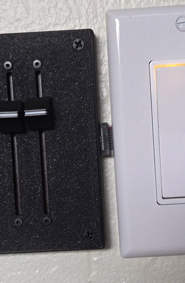
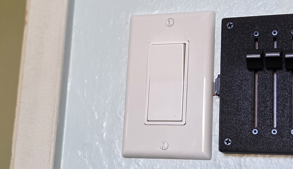
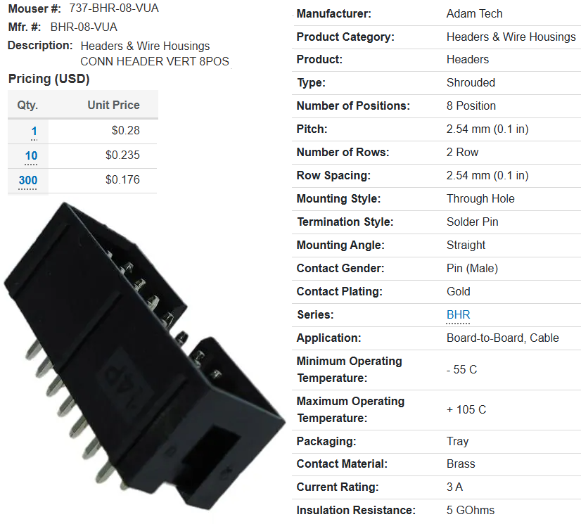
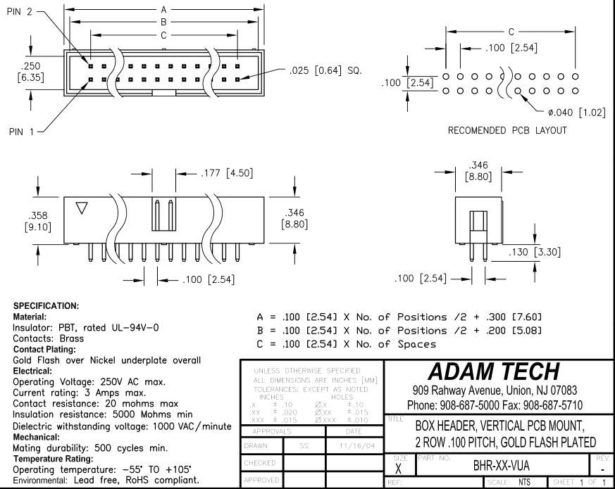
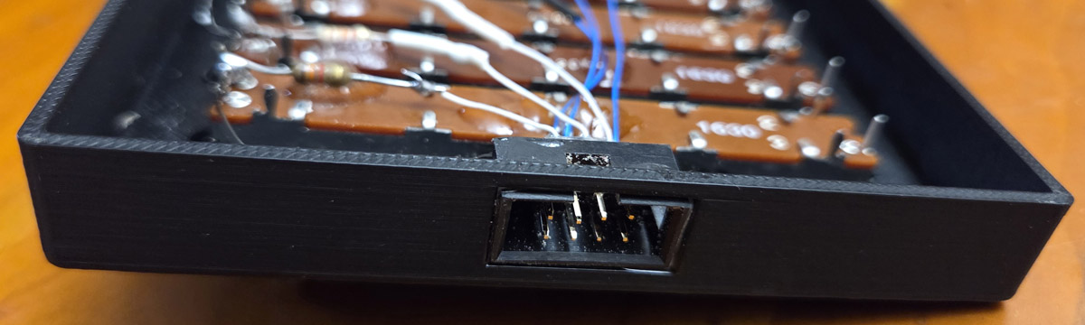 The picture on the left shows the male IDC connector inserted into the hole in the side of the dimmer enclosure
(and secured in place with a dab of epoxy). The cable shown above is inserted into this connector as the last
assembly step. The IDC connector was purchased from Mouser. You can see it's part number and specifications
here and it's mechanical drawing here.
The picture at the right shows the flat ribbon cable attached to the dimmer enclosure as the cable snakes out
of the switch box under the switch plate. Since you won't be yanking on this cable the strain relief isn't needed.
I snipped the strain relief off with a diagonal cutter. This gives the connection a lower profile and
allows the dimmer enclosure to be mounted closer to the switch.
The picture on the left shows the male IDC connector inserted into the hole in the side of the dimmer enclosure
(and secured in place with a dab of epoxy). The cable shown above is inserted into this connector as the last
assembly step. The IDC connector was purchased from Mouser. You can see it's part number and specifications
here and it's mechanical drawing here.
The picture at the right shows the flat ribbon cable attached to the dimmer enclosure as the cable snakes out
of the switch box under the switch plate. Since you won't be yanking on this cable the strain relief isn't needed.
I snipped the strain relief off with a diagonal cutter. This gives the connection a lower profile and
allows the dimmer enclosure to be mounted closer to the switch.
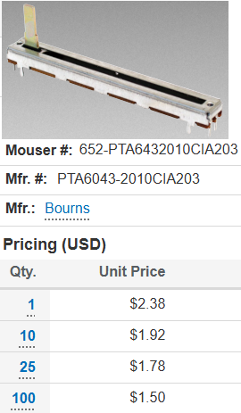
 I found that one of the difficulties of the commercial dimmers was that the slider used to control the brightness
had such a small travel (around 18mm), one of the reasons it was so difficult to use. So I decided to use a slider
with the longest travel I could find, which turned out to be the unit shown to the left (60mm travel). This slider
has an audio taper which as I mentioned before also makes the brightness easier to adjust. You can download the spec
sheet for this slider here.
I found that one of the difficulties of the commercial dimmers was that the slider used to control the brightness
had such a small travel (around 18mm), one of the reasons it was so difficult to use. So I decided to use a slider
with the longest travel I could find, which turned out to be the unit shown to the left (60mm travel). This slider
has an audio taper which as I mentioned before also makes the brightness easier to adjust. You can download the spec
sheet for this slider here.


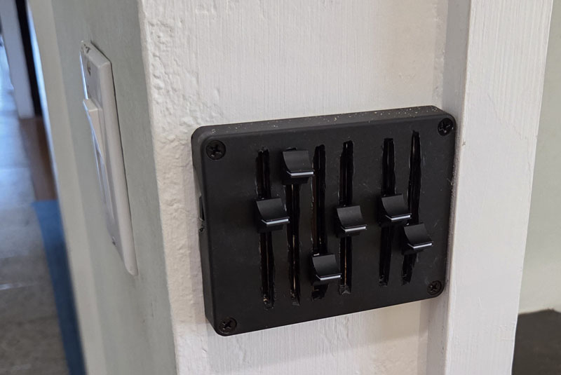 The first dimmer I built was for my family room which had a row of four lights on one side of the room and a row of
two lights on the other. I used the top of an electronics enclosure I happened to have and cut the slots for the
sliders using a dremel tool. I had no experience using the dremel tool and this was my first attempt which of
course looks terrible. If I was just going to build one I probably would have perfected my technique and tried again.
However I was planning on building many of these dimmers, so this method was going to be too time consuming.
The first dimmer I built was for my family room which had a row of four lights on one side of the room and a row of
two lights on the other. I used the top of an electronics enclosure I happened to have and cut the slots for the
sliders using a dremel tool. I had no experience using the dremel tool and this was my first attempt which of
course looks terrible. If I was just going to build one I probably would have perfected my technique and tried again.
However I was planning on building many of these dimmers, so this method was going to be too time consuming.
    Create an OpenScad design of a hollow 2mm thick box without a top.
    The bottom of the box is 100 mm by 70 mm (outside dimensions).
    The height of the box is 15 mm (outside dimension).

    Place 8 holes and 4 slots centered in the bottom of the box in this arrangement:

      x  ------------  x

      x  ------------  x

      x  ------------  x

      x  ------------  x

    Each x represents a 2.3 mm diameter hole.
    The spacing between each pair of holes in a row is 71 mm.
    The spacing between each row is 13 mm.

    Each string of 12 dashes represent a horizontal slot measuring 65 mm by 2.2 mm
    that is centered between the two holes on either side.
I was pleased to see that the chatbox's response was c code. (I've written hundreds of c programs so
I didn't have to learn any new syntax.) I copied the code from the chatbox into OpenScad and it
immediately rendered something. The design didn't match my description but the mistakes were obvious
and it didn't take me more than a few minutes to get a working design. I don't remember which chatbox
I used, but it was just a free model. Perhaps if I had used a professional model it would have come
up with the correct OpenScad code on the first try.
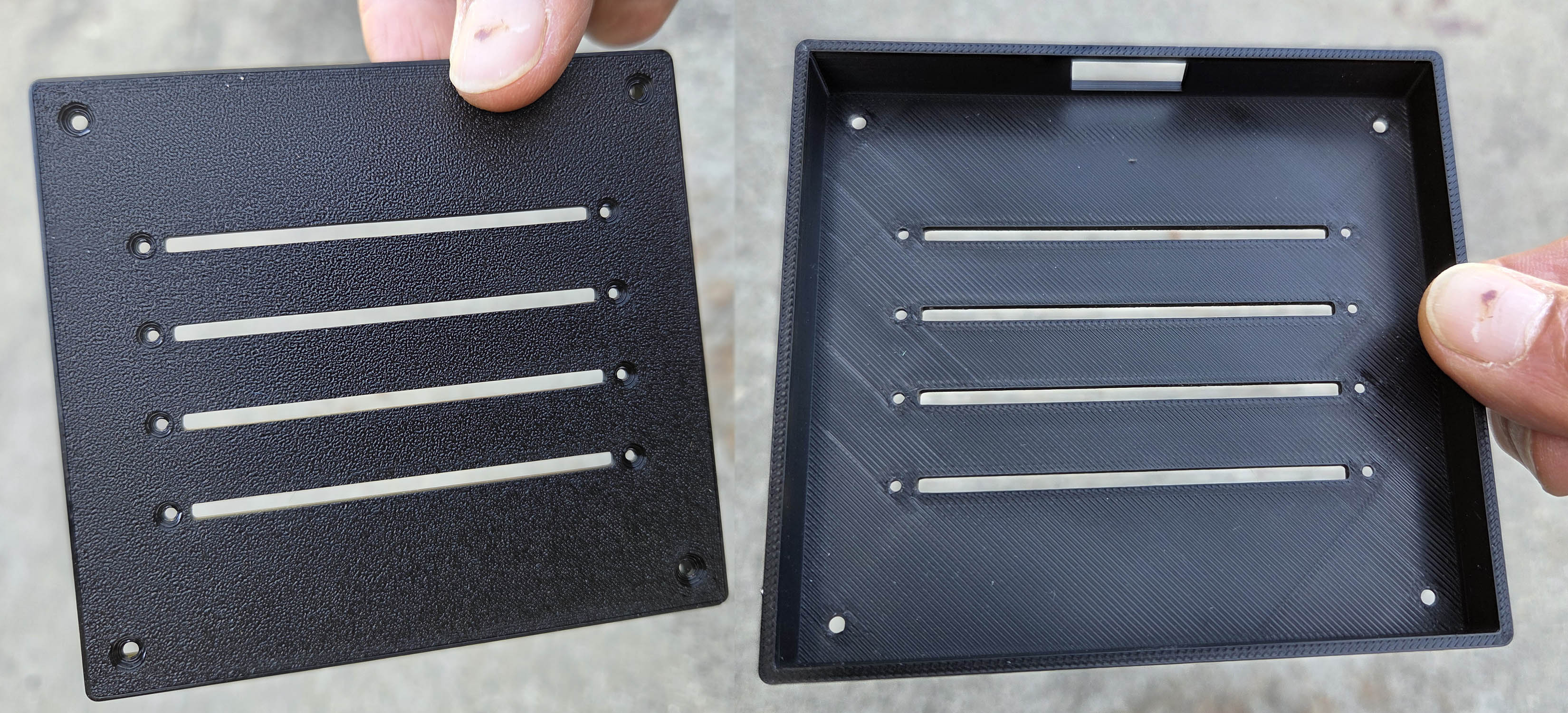
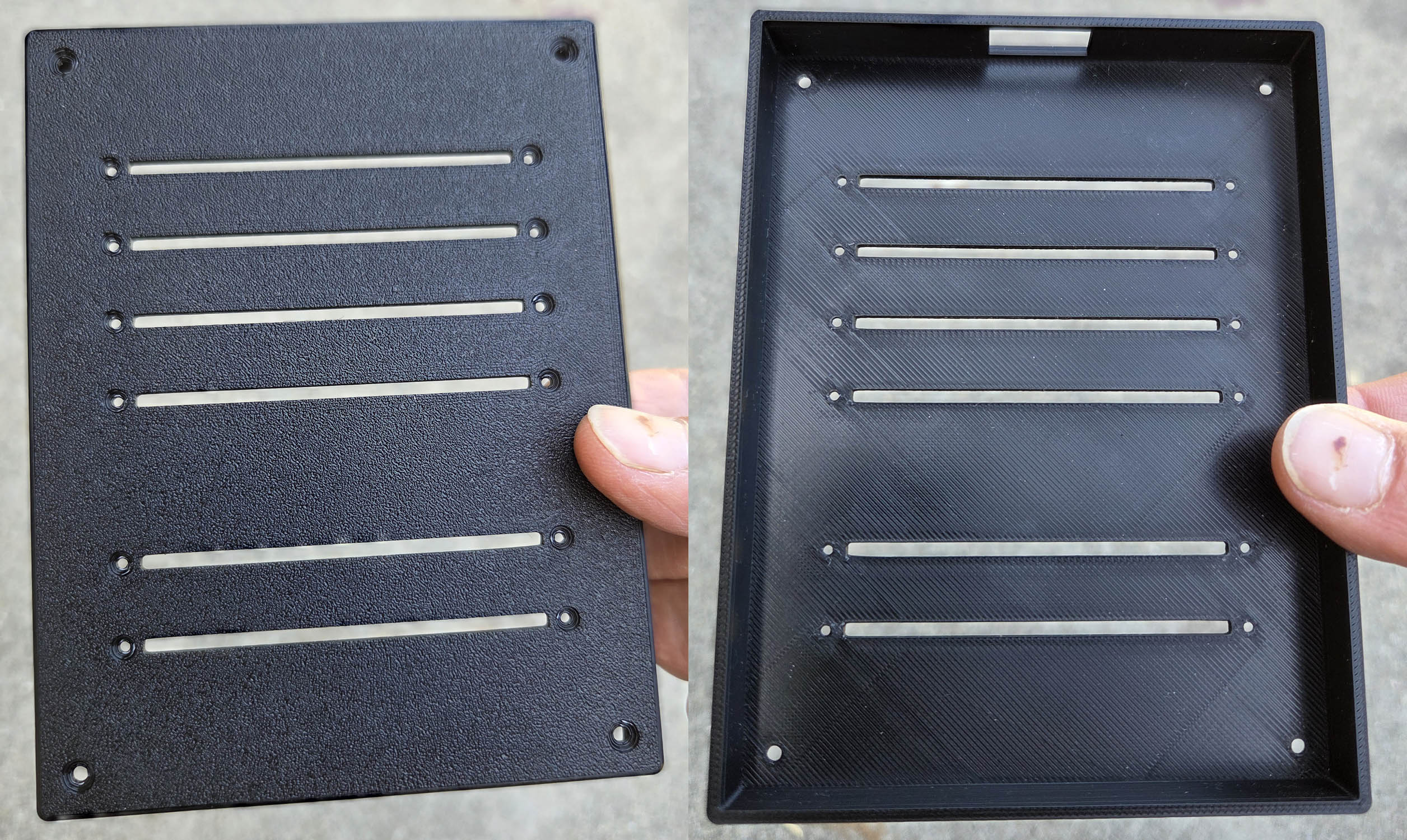
I added one feature that wasn't in my chatbox design spec (rounded corners) and then I was basically
ready to save the result as a .stl file to send to a 3d printing service. I was pleased that I was
able to use my very first try although I manually countersunk the corner mounting holes
so the screws would be flush with the surface. In my next iteration I added a countersink to the design
and also 3D printed these three additional configurations:
| # of sliders | .scad Code | .stl file | image | photo |
|---|---|---|---|---|
| 2 | download view | download | 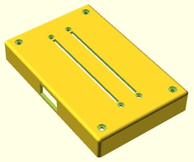
| Click on any image or photo for a full size view |
| 4 | download view | download | 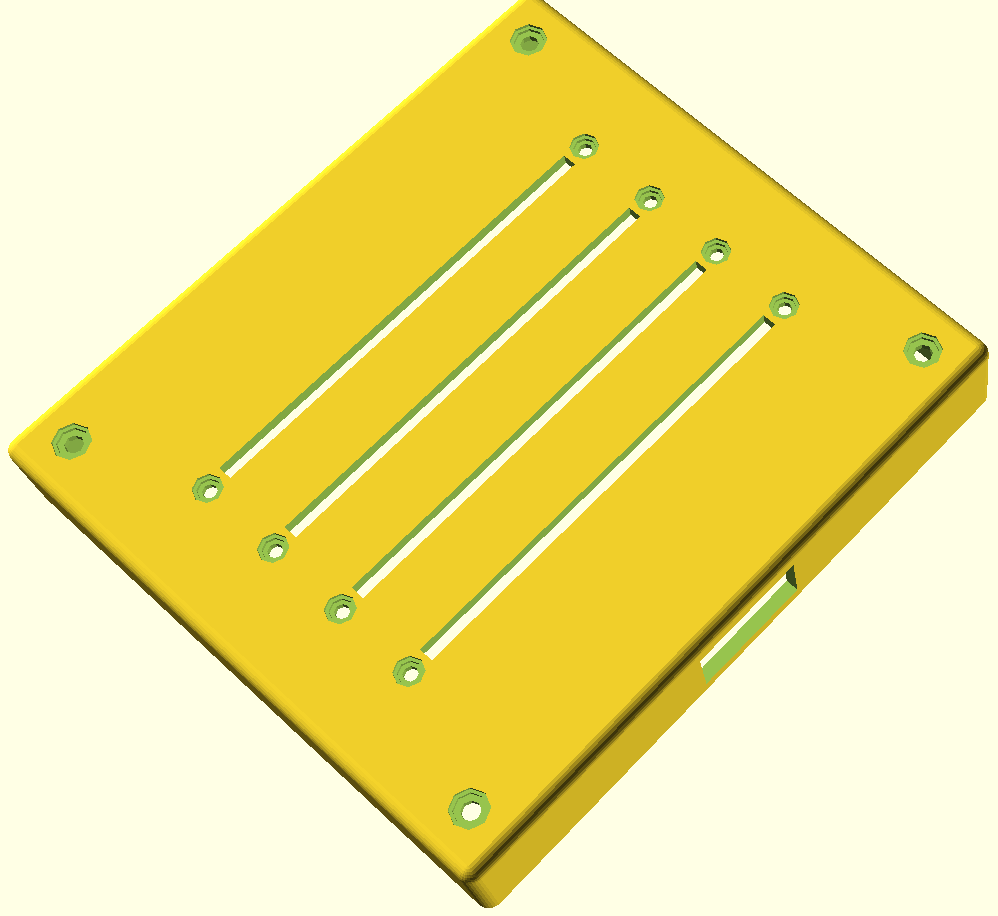
| 
|
| 6 (4+2) | download view | download | 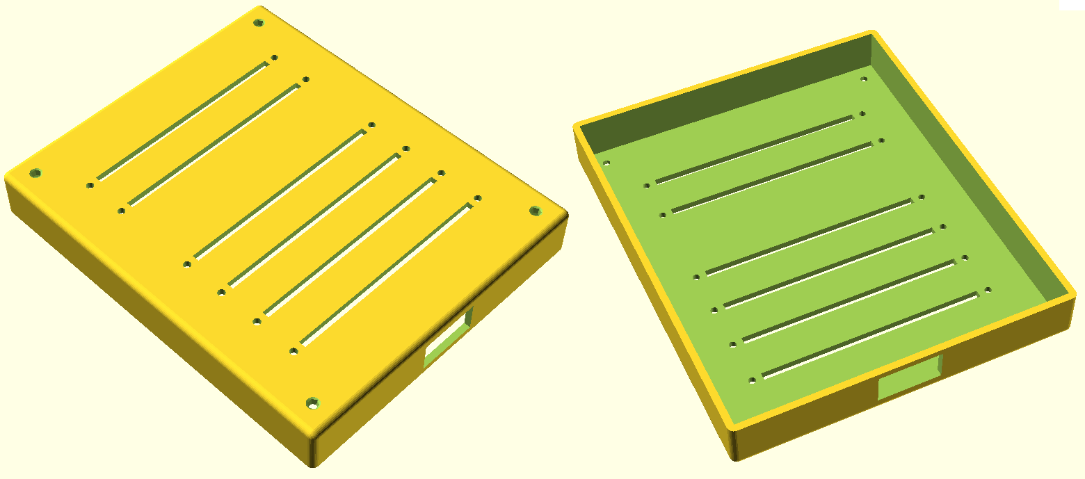
| 
|
| 6 (3+3) | download view | download | 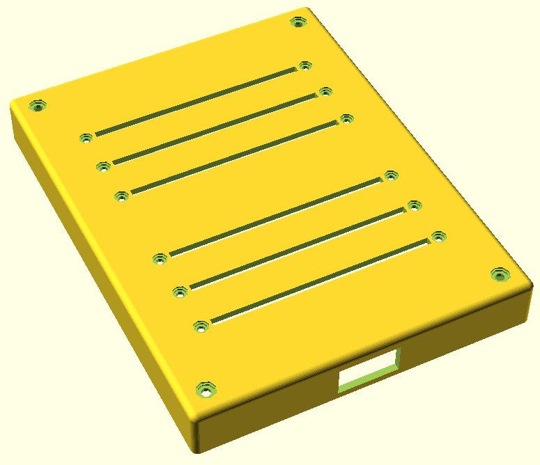
| |
| download view | roundedcube .scad | You must have this file on your path to render any of the above .scad designs. (used instead of the cube command) |
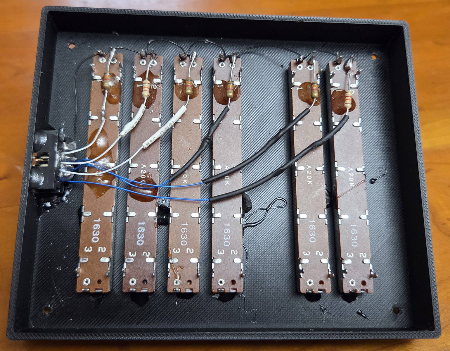
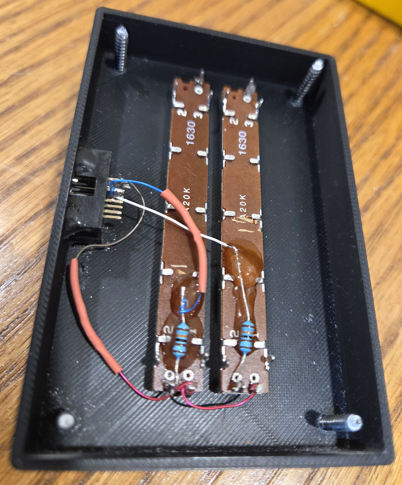
 The IDC connector is a press fit into the rectangular cutout in the enclosure but it isn't tight enough
to hold it securely. So I used a few dabs of epoxy to hold it in place. Although it isn't strictly
necessary, while I had the epoxy out I also used it to secure the wires and other components
in place. Note that you must use pins 1 and 2 of the slider potentiometer. If you used pins 2 and 3,
the slider would still control the intensity but the taper would reverse audio which would not be
appropriate. (Imagine the taper curve shown above, but upside down.) The picture to the right shows
the dimmer mounted to the right of the rocker switch. (In this case the dimmer had to be on the right
side since there isn't room to mount it on the left side of the switch.) This is the dimmer I used
in the family room and the master bedroom which both had a two rows of lights, one containing 4 lights
and the other with 2 (shown in the third row of the table above.) A similar dimmer with two rows of 3
lights was used in the living room (shown in the forth row of the table).
The IDC connector is a press fit into the rectangular cutout in the enclosure but it isn't tight enough
to hold it securely. So I used a few dabs of epoxy to hold it in place. Although it isn't strictly
necessary, while I had the epoxy out I also used it to secure the wires and other components
in place. Note that you must use pins 1 and 2 of the slider potentiometer. If you used pins 2 and 3,
the slider would still control the intensity but the taper would reverse audio which would not be
appropriate. (Imagine the taper curve shown above, but upside down.) The picture to the right shows
the dimmer mounted to the right of the rocker switch. (In this case the dimmer had to be on the right
side since there isn't room to mount it on the left side of the switch.) This is the dimmer I used
in the family room and the master bedroom which both had a two rows of lights, one containing 4 lights
and the other with 2 (shown in the third row of the table above.) A similar dimmer with two rows of 3
lights was used in the living room (shown in the forth row of the table).
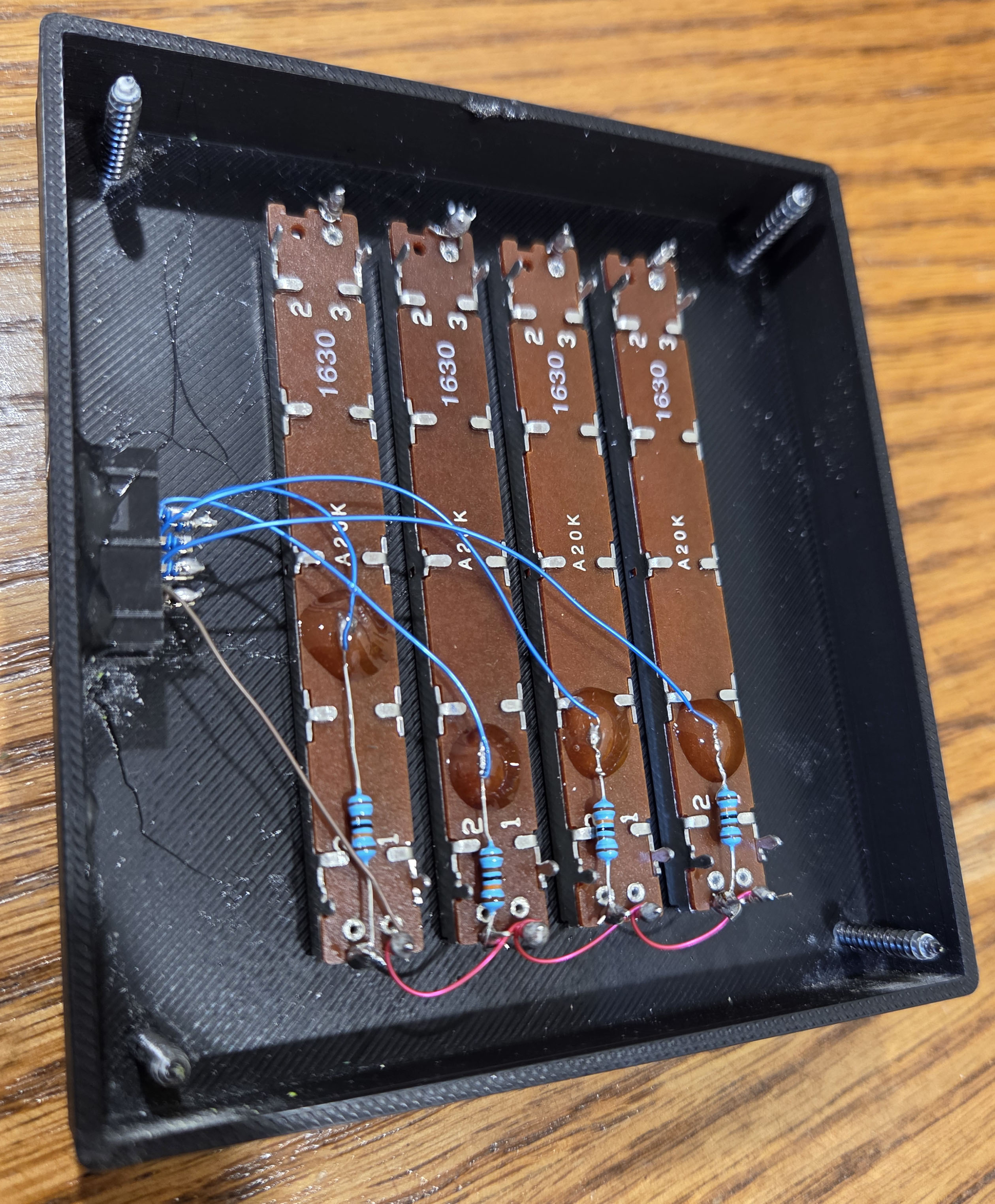
 In this case the dimmer had to be mounted on the left side of the rocker switch since there wasn't
room on the other side. Notice that the sliders are mounted in the opposite direction compared to
the six slider dimmer shown above. (This is necessary so that moving the slider up increases the
brightness.) As I mentioned before, it is easiest to connect the wires at random to any pin on
the IDC connector. This is most easily sorted out when attaching the female IDC cable to the
7 conductor cable. This was the dimmer used in the 3 bedrooms and the dinning area (shown
in the second row of the table above.)
In this case the dimmer had to be mounted on the left side of the rocker switch since there wasn't
room on the other side. Notice that the sliders are mounted in the opposite direction compared to
the six slider dimmer shown above. (This is necessary so that moving the slider up increases the
brightness.) As I mentioned before, it is easiest to connect the wires at random to any pin on
the IDC connector. This is most easily sorted out when attaching the female IDC cable to the
7 conductor cable. This was the dimmer used in the 3 bedrooms and the dinning area (shown
in the second row of the table above.)
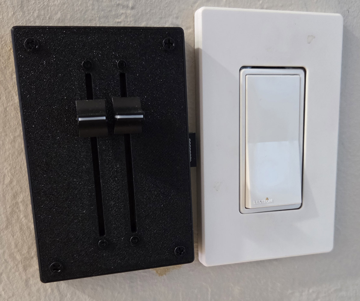 The simplest dimmer with just two sliders. The principles are the same, just fewer components.
This was the dimmer used in the master bedroom hallway (on a 3 way switch) as well as in the kitchen.
(Shown in the first row of the table above.)
The simplest dimmer with just two sliders. The principles are the same, just fewer components.
This was the dimmer used in the master bedroom hallway (on a 3 way switch) as well as in the kitchen.
(Shown in the first row of the table above.)
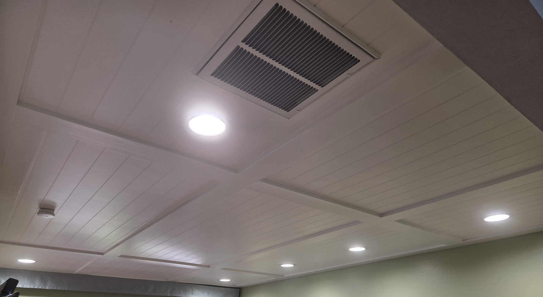 The six position dimmer shown above is used to control the lights in my family room pictured here.
The four lights along the back wall are above the couch which can take advantage of a lot of lighting.
The other side of the room has the TV and some shelving but no seating, so less light is needed there.
This explains my choice of the 4 + 2 configuration. I find that when I'm alone in my favorite spot to
read the newspaper, I have all the lights off except for the 2 lights directly above me. (My master
bedroom uses the same 4 + 2 configuration except 4 inch lights are used instead of the 6 inchers shown here.)
The six position dimmer shown above is used to control the lights in my family room pictured here.
The four lights along the back wall are above the couch which can take advantage of a lot of lighting.
The other side of the room has the TV and some shelving but no seating, so less light is needed there.
This explains my choice of the 4 + 2 configuration. I find that when I'm alone in my favorite spot to
read the newspaper, I have all the lights off except for the 2 lights directly above me. (My master
bedroom uses the same 4 + 2 configuration except 4 inch lights are used instead of the 6 inchers shown here.)
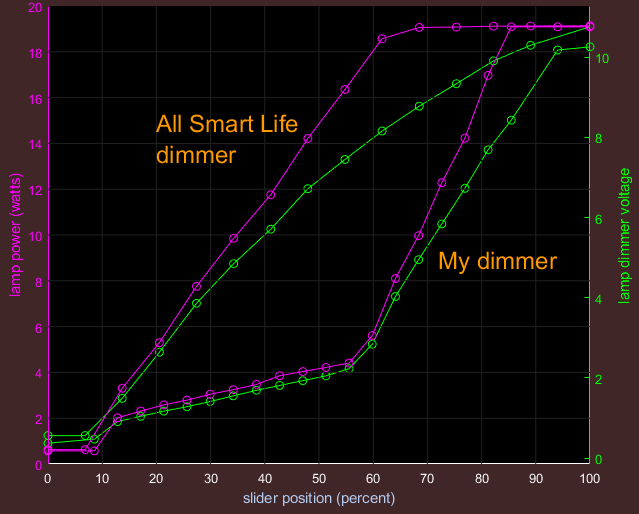
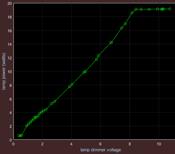 I made some measurements of the lamp's power vs. the slider position for my dimmer as well as the commercial dimmer
I had purchased. First I plotted lamp power vs. the dimmer control voltage (shown to the left). This is for a single 6 inch light.
This shows that the control voltage controls the lamp power approximately linearly with the maximum power achieved at about 8.3 volts.
(Perhaps they should have called it "0 - 8 volt dimmable".) Of course a different manufacturer might not have the same transfer
curve, although I suspect they would be similar. By the way, this data was collected by starting at the brightest end and slowly
moving the sliders down to the dimmest end. I didn't collect any data for moving the slider in the opposite direction but I know
that the results would be quite different. (This is called hysteresis.) In fact when starting at the bottom, one has to increase
the control voltage to around 2 volts before the lamp turns on. (I forgot to measure that, so this is a guess.) This means the
most significant dimming is only achieved by moving the sliders down. The script used to create this plot and the comparison
charts below can be found here
I made some measurements of the lamp's power vs. the slider position for my dimmer as well as the commercial dimmer
I had purchased. First I plotted lamp power vs. the dimmer control voltage (shown to the left). This is for a single 6 inch light.
This shows that the control voltage controls the lamp power approximately linearly with the maximum power achieved at about 8.3 volts.
(Perhaps they should have called it "0 - 8 volt dimmable".) Of course a different manufacturer might not have the same transfer
curve, although I suspect they would be similar. By the way, this data was collected by starting at the brightest end and slowly
moving the sliders down to the dimmest end. I didn't collect any data for moving the slider in the opposite direction but I know
that the results would be quite different. (This is called hysteresis.) In fact when starting at the bottom, one has to increase
the control voltage to around 2 volts before the lamp turns on. (I forgot to measure that, so this is a guess.) This means the
most significant dimming is only achieved by moving the sliders down. The script used to create this plot and the comparison
charts below can be found here
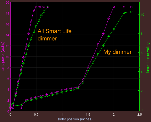 Here I plotted lamp power vs. slider position for the two dimmers.